project summary
- motion activated VCR recorder
- start/stop record
- sense VCR input mode
- command alley light on/off
- provide visual feedback
work summary
Cradle to Grave!
- Conceptualization
- Parts Selection
- Circuit Design
- Pcb Design
- Software Design
- Retrofitting
- Installation
- Troubleshooting
System Components
- Light Fixture
- Lights
- Motion Sensor
- VCR
- Video camera
- VCRBot
skills
- Circuit Design
- PCB Design
- Embedded Software Design (in C)
- Systems Integration
Background
After living in the same house for 4 years with no crime problems, two different cars were broken into in a two month period in the alley behind my garage, and several months later, the metal collectors that roam the alleys took several iron grates with which I was not ready to part and had placed in an area obviously not inviting their pillage. I will never know who the vandals, and in two of the cases thieves, were but as my human emotion (anger) turned to engineering emotion (analysis), I began to formulate a method to help me identify the subcretins if similar incidents occurred in the future.
There are several surveillance systems on the market, many of them computers or similar that record video digitally. They range in cost from a couple hundred dollars to thousands, and for my purposes, the cheaper end system would do. However, I decided to build my own recording system. Why?
- I already had a video camera in the alley. It just didn’t record to anything yet.
- What’s the fun in buying off the shelf? Designing this could be MUCH more fun!
- By designing my own, I would gain more experience with all aspects of a cradle to grave design.
To that end, I decided that my system would basically:
- be motion activated
- command a recording device to begin recording the video stream from the existing camera
- tell a recording device to stop recording
- optionally, turn on a light in the alley (the camera has night vision, but it’s poor
- provide me with feedback of the basic functionality of the system
System Components
- VCR –
- receive a video signal and transfer it to a recordable medium. I found this on craigslist for $5. The only important criteria were that it had to have physical switches for record and stop, and for proper feedback, it needed to have LED indicators for Record and TV/VCR Mode.
- Video Camera –
- produce a video signal. I already had one of these that I had bought at Harbor Freight for $30 several years ago. It had its own wallwart power supply and the video was transferred to two RCA connectors (video and monolog audio).
- Motion Sensor –
- determine when recording should begin and light should activate. See “Light” below.
- Light –
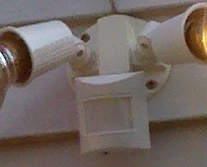
- shed light on the subject in the alley. I bought a two lamp floodlight with motion sensor at Lowe’s for $12.
- VCRBot –
- the circuit board that integrates all of the other components. See VCRBot sections below.
Light and Motion Sensor Preparation

The light and motion sensor were east to prepare. One can see by looking at the wiring that each of the lights is powered by a white wire which is common to both lights, the motion sensor, and the power source and a red wire that is common to the lights and the motion detector (not the power source). This means it is highly likely that the white is 120 VAC neutral and the red carries 120 VAC hot only when the motion sensor allows it to do so (it is a switched hot).

One can also see that the motion sensor has the source 120 VAC hot (black) and 120 VAC neutral entering it. This means that we must provide power to the motion sensor via the white and black, and beyond that, we can consider the motion sensor to be a motion activated relay (not far from the truth) that feeds 120 VAC hot out on the red wire when motion is sensed.
With these pieces of information, we now know that we can cut the red wire as marked (“Cut and Splice!”) in the picture at right. This separates the motion sensor output from the light inputs. We can then wire the motion sensor output side to a relay with 120 VAC coil, and when motion is sensed, our relay contacts will be closed. We can then wire the light input side of the red wire to the contact side of a different relay (the contacts should be rated for at least 120 VAC and 1.25A assuming 75W bulbs will be used).
Relay current rating > (bulb 1 wattage + bulb 2 wattage)/120
VCR Preparation

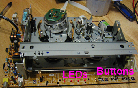
The VCR has two output points (with respect to our controller, inputs to the VCR) to which we need access and two additional input points (with respect to our controller, outputs from the VCR) to which access would be advantageous. A quick examination of the VCR’s front panel told me that all four points would be available in some way.
| Signal | INPUT from VCR or OUTPUT to VCR | VCR Component | Required |
|---|---|---|---|
| Record Command | OUTPUT | Button | x |
| Stop Command | OUTPUT | Button | x |
| Record Status | INPUT | LED | |
| TV/VCR Mode | INPUT | LED |

After disassembling the VCR, I noticed a bank of indicator LEDs, two of which were a record status LED and a TV/VCR mode LED. Using a multimeter, I found that all LEDs shared a common anode, which hovered around 4.6 volts but seemed inconsistent as multiple LEDs were cycled on and off. This indicated to me that I would be able to steal these signals, but it would be a good idea to keep them isolated from the rest of the VCRBot board.
I also noticed a bank of momentary pushbutton switches, two of which were the record and stop buttons. Using a multimeter again, I found that the switches were tied to ground on one side, so the component that reads the switches in the VCR is probably pulled up and looks for a low signal to indicate that a button has been pressed. Again, the power side of the switches was inconsistent, so isolation would be a good idea.
Because of the isolation, I now needed six wires: 2 LED signals, 2 switch signals, the common anode from the LEDs, and the common ground from the switches. Six solid wire telephone cable it is. I broke out all six points and brought the sheathed cable out the back of the VCR for a nice clean retrofit!
VCRBot Design
Components
Component selection was heavily influenced by what I already had on hand. The main parts are described in the table below.
| Part | Description | Chosen because it was on hand |
|---|---|---|
| Atmel AT90S2313 | 8 bit RISC microcontroller | x |
| 7 segment display | visual indicator | x |
| 4N25 optical isolators | instead of the VCR turning on its own LEDs, it will turn on the 4N25 LEDs so my micro can read that LED statuses and still be isolated | |
| NPN transistors | in parallel with VCR’s pushbuttons, used to close the switch contacts via the micro | |
| Relay 1 | 120 VAC coil, contacts used with low voltage as in input to the micro from the motion sensor | |
| Relay 2 | 3 VDC coil, contacts rated appropriately to turn on two floodlights |
Circuit
I used the free, non-commercial version of Eagle by CadSoft to draw the schematic, which can be seen below. The additional headers are for in system programming and hardwired switches to turn on and off the light and recording without software intervention. It should also be noted that the actual implementation replaced LED3 with a silicon diode because the LED’s forward voltage was too large and wouldn’t allow the relay coil to be activated. The easiest fix, without reproducing the pcb, was to use a diode with a lower forward voltage, which ended up being the silicon diode.


PCB (printed circuit board)

The PCB is a 2 layer design. The back layer, not shown here, consists mainly of surface mount resistors (pull-ups and current limiters for the LEDs) and capacitors (for the crystal).
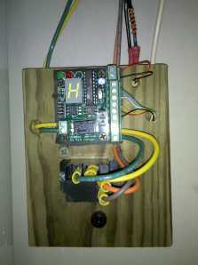
I used the free, non-commercial version of Eagle by CadSoft to design the pcb, which can be seen at right. From the design, I generated Gerber files that I sent to batchPCB for fabrication. Upon receiving the board, I populated all of the components, and after downloading the software, the VCRBot was alive! (see picture at left)
Software
I used Atmel’s AVR Studio along with WinAVR to write, compile, and assemble the software, which I wrote entirely in C. I then flashed the object file binary onto the board using Atmel’s AVR ISP software and the in system programming port that I had included in the pcb design.
System Functionality Specification
The following is just a general spec to give an idea of the overall system functionality.
The following assumes that the controller is not in an error state. Error states are described later.
- When motion is detected (Begin Recording)
- After a debounce time of 100ms on the motion sensor input, the record button is pressed for 200ms.
- If the record button is pressed, and the record status indicator does not indicate that the system is recording within 1 second of the button press, the button will be pressed again.
- The button press will be repeated as described above up to 4 times.
- If the record status indicator does not indicate that the system is recording after all attempts are complete, the system enters error state 2 (record button failed).
- After a debounce time of 100ms on the motion sensor input and a delay of 5 seconds, the light is turned on.
- After a debounce time of 100ms on the motion sensor input, the record button is pressed for 200ms.
- When the system is recording and motion has not been sensed for 60 seconds, the light is turned off
- When the system is recording and motion has not been sensed for 90 seconds, the stop button is pressed (Stop Recording)
- If the stop button is pressed, and the record status indicator does not indicate that the system has stopped recording within 1 second of the button press, the button will be pressed again.
- The button press will be repeated as described above up to 4 times.
- If the record status indicator indicates that the system is recording after all attempts are complete, the system enters error state 3 (stop button failed).
- When the system starts recording, it will be at least 5 seconds before the stop recording sequence, including the light deactivation, is initiated.
- When the system stops recording, it will be at least 10 seconds before the start recording sequence, including the light activation, is initiated.
When the system is in an error state,
- The 7 segment display will flash “E” followed by an error number until the error is cleared. The 7 segment display updates every second.
- The light will cycle on when motion is sensed and off when motion is not sensed with no delays.
The following are the error states.
| Error Code | Description | Cause |
|---|---|---|
| 0 | No error | No error is detected |
| 1 | TV Mode | The VCR input mode is in TV mode instead of VCR mode. Recording will result in static rather than the camera signal. |
| 2 | Record Failed | The record button has been pressed several times, and the record status indicates that the system is still not recording. |
| 3 | Stop Failed | The stop button has been pressed several times, and the record status indicates that the system is still recording. |
| 4 | Record without Request | The record button was not pressed, and the system had not logically entered record mode, but the record status indicates that the VCR is recording anyway. |
The 7 segment display:
- updates every second.
- will display any current error codes as described in the error state section.
- Will display a rotating pattern when the system is ready to record (not in an error state) but is not currently recording.
- will flash an “R” character when the system is recording and is not in an error state.
- will flash the decimal LED on and off each second while the light is commanded on.
Final Results

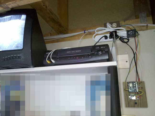
See for yourself! Check out the pics here. I mounted the PCB on a 1×4 piece of scrap wood, and I drilled holes vertically through the wood to run the wires without making a mess. Below the PCB is the motion detector relay, and below that is a push on/push off switch that can be used to turn the light on regardless of the state of the system (it’s a light activate override, or light “Hand”).


