project summary
- 2 Helmets
- LED Effects
- local, low budget kids’ film
- several day time frame
skills
- Circuit Design
- Embedded Software Design (in C)
- Fabrication
- Quick turn!
Background
Some friends of mine wanted an extra prop for their annual film project starring kids from their church. The setup is as follows:
Two young girls, spies with high tech facilities and gadgets, need to brainstorm an idea together, so they put on their helmets and activate the “thinktank”. The helmets allow their thoughts to be displayed on a movie screen so that they can visually share their thoughts and ideas with each other. The helmets had no particular design or requirements except that they should look high tech (for a kids’ movie).
System Components
- Salad Bowls –
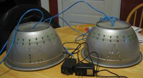
- Painted silver, the bowls made great inexpensive helmets.
- LEDs –
- The helmets were adorned with LEDs for the high tech look.
- Power and Control Box –
- Something has to power and control the LEDs!
- Wire and Cable –
- recommended for electron flow within and between the helmets
Basic Layout

Each helmet has red (clear when off) LEDs in the shape of it’s character’s first initial. These letters pulse on and off when the thinktank device is inactive, and will transition to a fully illuminated state when the thinktank device is in use by the characters.
Above the initials are two rows of green LEDs which will be off when the thinktank is inactive and will “chase” or “sequence” at an increasing rate as the thinktank transitions to its active, or in use, state.
The helmets are connected by a ethernet blue cable that exits/enters through the top of each helmet. As part of the prop, this serves as a means of connectivity for the thinktank, but in reality, it is a way to power one helmet from the other and ensure that both helmets are synchronized since corresponding LEDs from opposite helmets will be driven by the same signal.

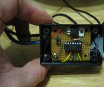
Behind the scenes, there is a small control box that connects to one of the helmets. The control box contains a very simple controller consisting of a microcontroller, some voltage level circuitry, a power port, and an optional 9 volt battery which can be used in place of a 9 volt wall transformer plugged into the power port. The control box also has a SPST switch to tell the controller when the thinktank is activated or deactivated.
Part Selection
Mid Level Design
Each helmet has 5 channels, or independent LED driver signals: 1 for the red letter, and 4 green LED channels split evenly amongst the eight columns (1&5, 2&6, 3&7, 4&8) so that they can chase correctly. Since both helmets share the same 5 driver signals, this means that the cable from the control box needs seven wires: power, ground, and five driver signals, and the cable between the two helmets has the same seven wires. The microcontroller controls the driver signals, which turns on and off multiple NPN transistors, each of which turns on and off multiple LEDs using the 9 volt power and a current limiting resistor. The micro also reads a SPST switch. All of this will be assembled by hand, so through hole parts are recommended.
Controller
I already have the hardware and software to program Atmel AVRs, so I chose to go with one of those for the microcontroller. The only real requirements for me were an internal oscillator and 6 I/O pins. Based on these, I chose the Tiny44A, which comes in a 14 pin DIP. To program it in circuit, I needed a 6 pin .1″ pitch header (2×3), and to power it properly, I used a 7805 voltage regulator with a 10uF capacitor (slightly undersized) which is hidden under the board in the pictures. I also pulled up the RST’ pin with a 10k resistor. I suppose I didn’t have to use a resistor on this chip, but I usually do anyway, and they’re cheap.
LEDs

I used 5mm LEDs all around and designed for close to 20mA, give or take 25% (yes, that’s close enough for this!). Since the micro can only drive an LED or two (if you’re lucky), and I’d prefer to drive an entire channel with one signal from the micro, the LEDs are driven by common NPN transistors, 2n2222a or equivalent, and a current limiting resistor. With a 9 volt supply on the transistor collector, a 1 volt Vce, and 1.5 volt Vf on the LEDs, each transistor, saturated, can drive ((9-1)/1.5)=5 LEDs.
The green LEDs have 4 LEDs per channel (per helmet also), so each of the green channels in each helmet needs one transistor. The letter L has a total of 6 LEDs, so it will require 2 channels. I chose to split it in half, putting 3 LEDs on each transistor. The letter A has a total of 10 LEDs, so it will require 2 transistors, each driving the maximum 5 LEDs. Before you start complaining about how to calculate a current limiting resistor based on a zero volt drop across it, rest assured that the 9 volt supply is a bit higher than 9 volts (especially from the wall transformer), but I’ll spare you the details.
Final Results
Here are some videos. See for yourself! Although, I have to say that the video doesn’t do the helmets justice. It’s hard to film light sources and make them look good.

