project summary
- 2 motion detectors
- 2 lights
- dual 120V HOA (on/off/auto)
- configurable timer for each light
- configurable motion source
- provide visual feedback
work summary
Cradle to Grave!
- Conceptualization
- Parts Selection
- Circuit Design
- Pcb Design
- Software Design
- Installation
- Troubleshooting
System Components
- Light Fixtures
- Lights
- Motion Sensors
- Dual gangbox with blank faceplate
- Custom Controller
skills
- Circuit Design
- PCB Design
- Embedded Software Design (in C)
- Systems Integration
- 120 VAC Wiring
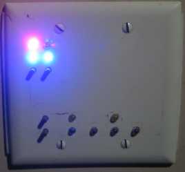
Background
I added a hot tub to my back yard, and I tend to use it more at night than in the daytime. The night sky full of stars, great company, radiofreetexas.org playing on my outdoor speakers, an occasional airplane passing overhead, and a motion sensing outdoor light that turns on and off constantly – the perfect ambiance for great relaxation, right? I guess we could do without the airplanes and the light turning on and off. Unfortunately, we can only control one of those, so why not do it? What would be nice is an HOA switch for the light. An HOA switch, short for Hand/Off/Auto switch, is a 3 position switch that controls a load to be constantly on (Hand), constantly off (Off), or controlled on and off by an automation system or device (Auto). HOA switches are common in industrial controls, but very few exist for house wiring applications, and the couple I found at Grainger were about $90 each. Why would they have to be made for house wiring applications? The answer lies mainly in the installation of the device. I don’t want something on the outside of my house that looks like an industrial switch, and it would be nice if the switch would fit in common house wiring enclosures, some of which are called gangboxes.
As long as I am going to install an HOA switch for the yard light, I might as well install one for the porch light as well. The porch is covered and has an exterior globe light under the roof. The switch for the light had been removed already when I rebuilt the porch and roof, so the light needed a new switch anyway.
So now the scope includes two HOA switches, and given the expense of the HOA switches at Grainger, I decided to make my own digital dual HOA switch with a little extra configurability. My basic requirements/functionality are as follows:
- PCB should be installed in a dual gangbox
- the circuit should be powered by 120 VAC only
- control 2 lights independently with 2 motion sensors
Mode # Description> 0 Motion 1 activates Light 1
Motion 2 activates Light 21 Motion 1 activates both lights 2 Motion 2 activates both lights 3 Both lights are activated when EITHER Motion is tripped - each light has its own configurable stay on time
- provide user feedback as to the HOA state of each light
System Components
- Motion Sensors –
- determine when to activate each light. See “Light” below.
- Light –
- shed light on the back yard or the covered porch. I bought two dual lamp floodlights with motion sensor at Lowe’s for $12. I removed the lights from one of them to use only the motion sensor because the porch light was arleady in place.
- Dual gangbox with blank faceplate –
- the enclosure for this design. The faceplate would need drilled in a few places to expose LEDs and push buttons.
- Custom Controller –
- the PCB and circuitry to read motion sensor signals and enable power to the lights as configured by the user.
Light and Motion Sensor Preparation
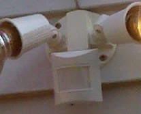
The light and motion sensor were easy to prepare. One can see by looking at the wiring that each of the lights is powered by a white wire which is common to both lights, the motion sensor, and the power source and a red wire that is common to the lights and the motion detector (not the power source). This means it is highly likely that the white is 120 VAC neutral and the red carries 120 VAC hot only when the motion sensor allows it to do so (it is a switched hot).

One can also see that the motion sensor has the source 120 VAC hot (black) and 120 VAC neutral entering it. This means that we must provide power to the motion sensor via the white and black, and beyond that, we can consider the motion sensor to be a motion activated relay (not far from the truth) that feeds 120 VAC hot out on the red wire when motion is sensed.
With these pieces of information, we now know that we can cut the red wire as marked (“Cut and Splice!”) in the picture at right. This separates the motion sensor output from the light inputs. We can then wire the motion sensor output side to a 120 VAC input on the controller. We can then wire the light input side of the red wire to enable/disable the light’s power through the controller.
Digital Dual HOA Controller Design
Components
Microcontroller selection was heavily influenced by what I already had on hand, and other parts were selected based on cost and short term availability. The main parts are described in the table below.
| Part | Description |
|---|---|
| POWER | |
| Pulse 030-7151 | 120 VAC -> 9V, 166mA transformer |
| 1N4004 | diodes for full bridge rectifier |
| 7805 | 5 volt regulator |
| CONTROL | |
| Atmel AT90S8515 | 8 bit RISC microcontroller |
| MID400 | AC line monitor – reads when motion detectors are active |
| MOC3010 | Opto isolators with triac drive output |
| BT138 | Triac for light enable/disable |
| INTERFACE | LEDs | visual indicators |
| pushbuttons | user input, momentary mini pushbutton switches |
Circuit
I used the free, non-commercial version of Eagle by CadSoft to draw the schematic, which can be seen below. The user interface includes 4 pushbuttons and 10 LEDs of various colors. There is a transformer and voltage regulator to provide power to the digital circuitry, AC line monitors to receive a 120 VAC input from the motion sensors, triacs to drive the outdoors lights, and optical isolators to isolate and allow the microcontroller to enable/disable the triacs. Two additional headers are provided: one for programming the microcontroller via JTAG, and one for an I/O expansion board. I have not built or designed the expansion board, and I may never do so, but the intention for that would be to allow a wireless remote to command the dual HOA controller.


PCB (printed circuit board)
The PCB is a 2 layer design. The back layer consists of power and controller parts including the transformer, voltage regulator, full wave rectifier, microcontroller, line monitors, triacs, triac drivers, headers, and a shift register used for I/O. The front, of course, has all of the user interface parts – LEDs and pushbuttons.
I used the free, non-commercial version of Eagle by CadSoft to design the pcb, which can be seen at right. From the design, I generated Gerber files that I sent to batchPCB for fabrication. Upon receiving the board, I populated all of the components, and after downloading the software, the controller was alive!
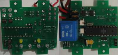
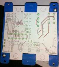
As seen here, the pcb design was made to fit in a dual gangbox for easy house installation and conformance to wiring codes.
Software
I used Atmel’s AVR Studio along with WinAVR to write, compile, and assemble the software, which I wrote entirely in C, using an object oriented approach as I created structs and utilized data hiding and C equivalent of member functions for a light, a timer, a pushbutton, etc. that all handle their own debouncing, timing, reading, etc. I then flashed the object file binary onto the board using Atmel’s AVR ISP software and the in system programming port that I had included in the pcb design.
System Functionality Specification
The following is just a general spec to give an idea of the overall system functionality.
Normal Operation
- When motion is detected by a motion sensor, activate any light that is in auto and associated with the motion sensor and reset that light’s On Time counter to 0. The motion sensor inputs are debounced appropriately.
- The motion LEDs will indicate when each motion sensor is telling the controller that motion has been sensed.
- Lights stay on when they are activated until their On Time counter reaches the configured number of minutes (configurable for each light).
- HOA – each light has an independent HOA selector.
- Hand (on): when a light is in hand, the light remains on indefinitely and the HOA indication LED also remains on indefinitely.
- Off: when a light is in off, the light remains off indefinitely and the HOA indication LED blinks briefly once every 3 seconds.
- Auto: when a light is in auto, it is controlled by the motion sensor(s) with which the light is associated and the HOA indication LED fades in and out.
- The Master LEDs will show which motion sensors control each light as follows:
Mode # Description> Master 1 LED Maaster 2 LED 0 Motion 1 activates Light 1
Motion 2 activates Light 2– – 1 Motion 1 activates both lights ON – 2 Motion 2 activates both lights – ON 3 Both lights are activated when EITHER Motion is tripped ON ON - The time LEDs will chase left to right and then back every 5 seconds or so to show that the controller is still functioning at all times and to add cool effect.
- User settings (HOA state for each light, Master mode, on time for each light) will be saved to EEPROM after being changed, and these settings will be restored to the controller in the event of power loss and recovery or system reset.
User Configurability
- HOA: Each HOA pushbutton press will cycle through Hand (on), Off, and auto modes one press at a time.
- Master Motion Sensor: Each Master pushbutton press will cycle through the four Master modes one press at a time.
- Light Time: To configure the time that a light remains on after motion is sensed, the user would do the following:
- Hold down the HOA button corresponding to the light (yard or porch) that needs time adjustment.
- A Time LED will begin blinking. The blinking LED indicates the number of minutes that is the current setting for the selected light. Do not release the HOA button.
- Press the Time button until the desired number of minutes (options are 1, 5, 10, and 30) is indicated by the blinking LED.
- Release the HOA button.
- The new setting will be saved to non volatile memory after 30 seconds. If a loss of power occurs within this time, the setting will return to the previous setting.
Faceplate
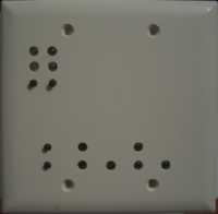
To finish the preparation for installation, and to make the device look like it was intended for residential application and installation, I modified a blank dual gangbox faceplate, drilling holes for the user interface LEDs and switches. Because the controller would be installed on the house exterior, I also used an insulation pad between the board and the faceplate to help prevent moisture issues even though the switch is under the roof of a covered porch. You can’t be too careful!
Of course a nice label for the user interface will be a nice touch…


